Hardware Documentation: Darius
Supports a 64-bit instruction set on Intel® 64 architecture which delivers 64-bit computing on server, workstation, desktop and mobile platforms when combined with supporting software. This Intel 64 architecture improves performance by allowing it to address 8 GB of physical memory.
Supports Intel® Virtualization Technology (VT-x) allows one hardware platform to function as multiple “virtual” platforms. It offers improved manageability by limiting downtime and maintaining productivity by isolating computing activities into separate partitions.
Supports Enhanced Intel SpeedStep® Technology is an advanced means of enabling high performance while meeting the power-conservation needs of mobile systems. Conventional Intel SpeedStep® Technology switches both voltage and frequency in tandem between high and low levels in response to processor load. Enhanced Intel SpeedStep® Technology builds upon that architecture using design strategies such as Separation between Voltage and Frequency Changes, and Clock Partitioning and Recovery.
| Specifications | |
|---|---|
| Total Cores | 2 |
| Total Threads | 2 |
| Maximum Memory | 8 GB |
| Memory Type | DDR3L 1333 |
| Burst Frequency | 2.58 GHz |
| Base Frequency | 2.16 GHz |
| Cache | 1 MB L2 Cache |
| Average Power | 7.5 W |
| Processor Number | N2840 |
Measurements and scales
120mm wide
120mm long
15mm tall
200 grams without SSD or RAM
Note
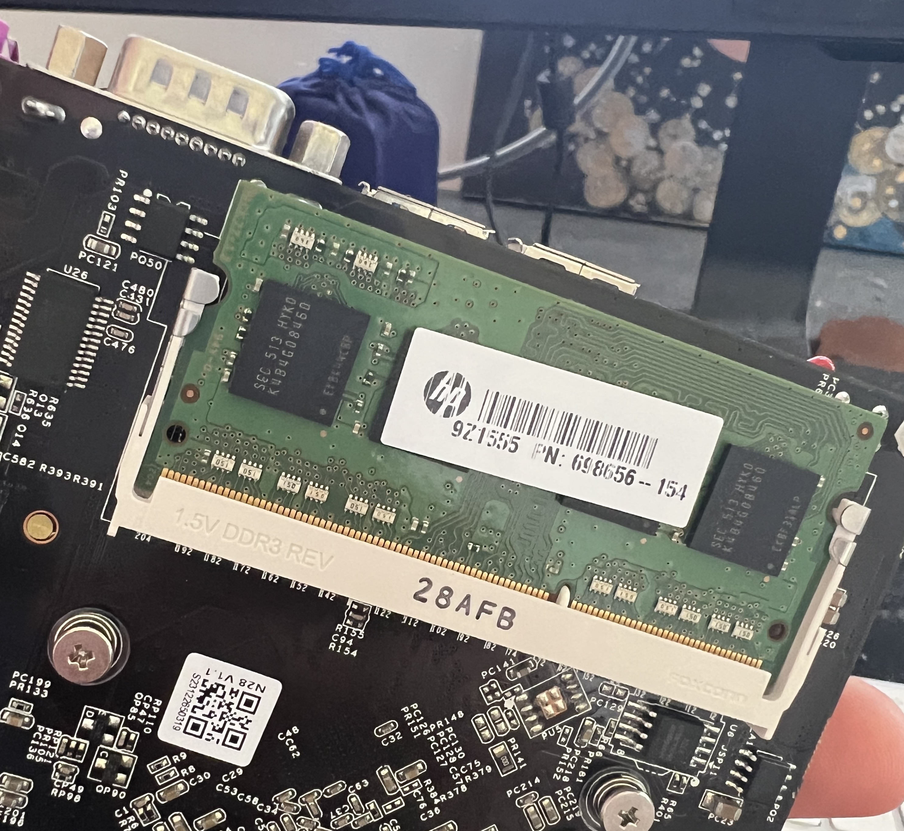
Screw holes are M3 and require a minimum 15mm standoff for the RAM mounted on the underside.

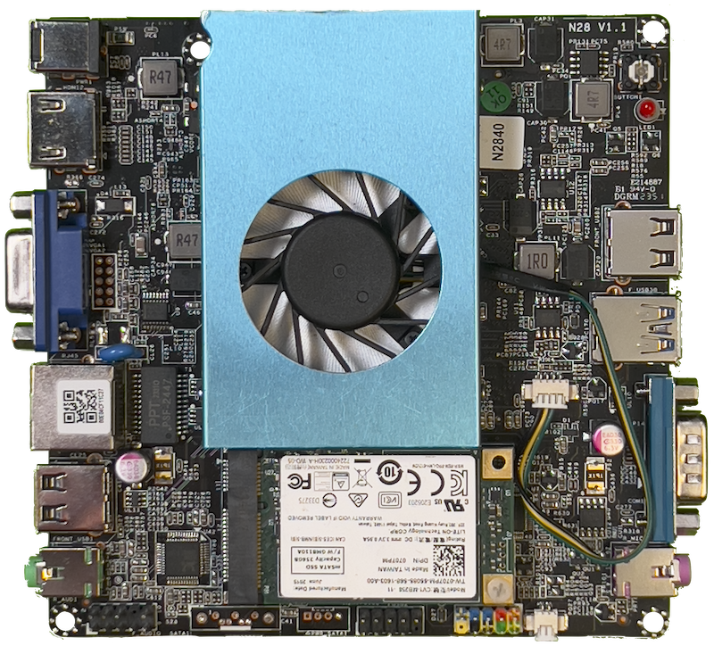
Image of top side
The board is designed to maintain a slim profile. The RapidAnalysis custom case for the Darius is 30mm thick. As long as the attached active cooling fan is not blocked, your own custom cases can reduce this profile significantly.

Block Diagram
Please see the block digram illustrating ports and interfaces below, following the same orientation as the board image above.

Internal GPU Spec (OpenVino)
Intel® HD Graphics for Intel Atom® Processor Z3700 Series.
Pin Specifications
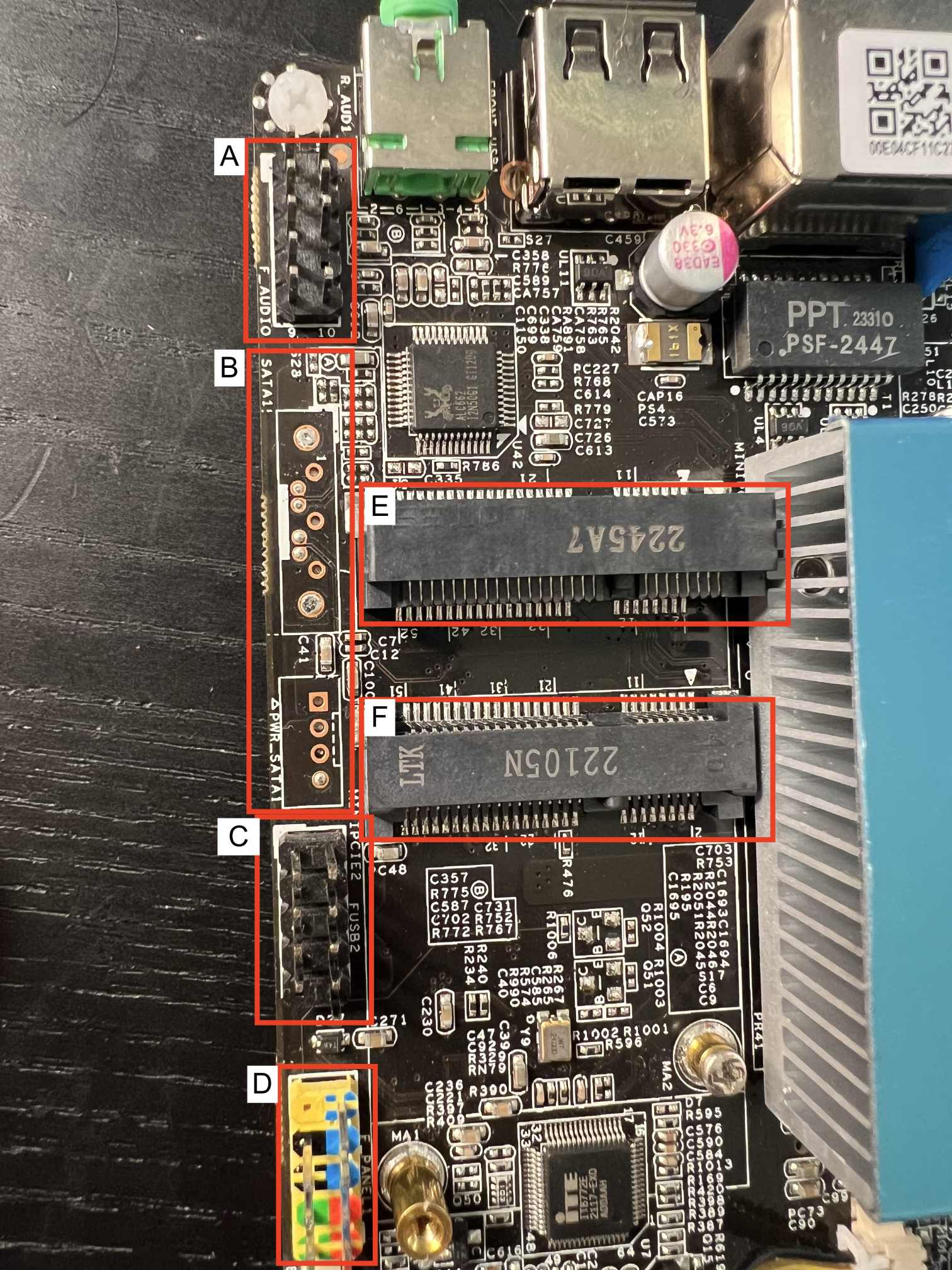
The following pin specifications reference the image below.

Pin Header (A)
| Pin | Definition |
|---|---|
| 1 | Microphone 2 Left |
| 2 | Audio Ground |
| 3 | Microphone 2 Right |
| 4 | VCC 3P3 S |
| 5 | Line 2 Right |
| 6 | Microphone 2 JD |
| 7 | Front I/O |
| 8 | KEY (No Pin) |
| 9 | Line 2 Left |
| 10 | Line 2 JD |
Through Hole (B)
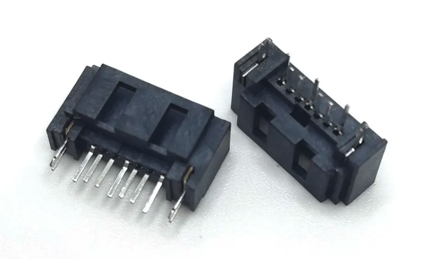
SATA Connector, 1*7 Pin, female socket, DIP, with harpoon board lock.

Pin Header (C)
| Pin | Definition |
|---|---|
| 1 | Power (+5V) |
| 2 | Power (+5V) |
| 3 | USB DX- |
| 4 | USB DY- |
| 5 | USB DX+ |
| 6 | USB DY+ |
| 7 | GROUND |
| 8 | GROUND |
| 9 | KEY (No Pin) |
| 10 | No Connect |
Pin Header (D)
| Pin | Definition |
|---|---|
| 1 | HDD-LED+ |
| 2 | PWR-LED+ |
| 3 | HDD-LED- |
| 4 | PWR-LED- |
| 5 | GND |
| 6 | PWR-SW |
| 7 | FP-RSR |
| 8 | GROUND |
| 9 | No Connect |
| 10 | Key (No Pin) |
mSATA Connector (E & F)
Stacked mSATA connectors for connecting any 2 mSATA compatible devices. Please see the Peripherals section for more details about compatibility.